Analog Signal Analogue: Types Of Signal, Differences, And Uses
Applications of Analog Signals
Analog signals are very important in electrical engineering and electronics. They often appear as changes in voltage and current. Continuous signals are common in nature. They show up as continuous variables such as temperature, wind speed, pressure, humidity, and pH levels.
But what exactly defines an analog signal? This article looks at what it is, the different types, its uses, and how it compares to digital signals.
What is an Analog Signal?
An continuous signal is a steady electrical signal. It shows a variable that is being measured. These signals can be described by voltage or current. Their amplitudes relate to the range of the measured parameter.
Think of an continuous signal like a light dimmer switch. When you change it, the brightness changes smoothly. It does not jump between set levels.
In nature, most physical quantities change in a smooth way. For example, temperature changes smoothly over time. It takes a specific value at any moment, no matter how brief.
Uninterrupted changes are the main feature of analog signals. These signals can be divided in time and size. However, it is not possible to achieve perfect precision.
Types of Standard Analog Signals
Sensors mainly produce types of signal: analog voltage and analog current.
**Analog Voltage Signals**
– *0-5V Signal*: A common format is used to show measured values between 0 and 5 volts. This low-voltage method works well for short-distance transmission. It is often used in small devices, control systems, and data collection tools.
– *0-10V Signal*: The 0-10V signal offers a wider range than 0-5V. It can handle larger changes in analog values. Here, 0V represents the lower limit while 10V is the upper bound.
With a higher resolution than 0-5V signals, it provides more accurate measurements. This makes it good for applications that need finer control.
**Analog Current Signals**
– *4-20mA Signal*: This signal is commonly used in industrial control systems. It is known for staying stable over long distances. Current signals are less affected by line resistance than voltage signals. This helps make sure we perform well.
In this system, 4mA is the lowest measurable value. Meanwhile, 20mA is the highest. Using 4mA as the starting point instead of 0mA helps find faults better.
Current signals usually work with a standard 24V DC power supply. This helps ensure they function reliably.
**Key Differences: 4-20mA vs. 0-10V vs. 0-5V**
Both 0-5V and 0-10V are types of analog voltage signals. The 4-20mA signal is a type of analog current signal.
The *0-5V Signal* is popular for short-range uses and embedded systems. It is easy to use and works well with microcontrollers like STM32, Arduino, and ESP32.
These microcontrollers usually have ADC inputs for the 0-5V range. This allows direct integration without needing extra parts for signal conditioning or isolation. This makes development faster and more efficient.
The *0-10V Signal* is widely used in HVAC systems and automation. It is reliable and easy to troubleshoot. By doubling the resolution from 0-5V at the same ADC precision, it allows for more detailed signal measurements. This makes the system work better in situations that need improved detection and control.
The *4-20mA Signal* works well in industrial settings. It is good for long-distance transmission and is very reliable. Its sensitivity to outside interference is low compared to voltage signals. This makes it a better choice for tough tasks, like process control in factories.
Knowing these differences helps engineers and designers choose the right signal type for each use. This helps the system work well in various applications.
Voltage signals have some drawbacks to think about:
– They are highly prone to electrical noise and interference.
-Sensors that use voltage signals need a separate power wire. This is in addition to the two signal wires.
-Long cable runs can cause voltage drops. This can hurt the accuracy of measurements.
– A 0V reading cannot tell the difference between a zero measurement and no signal. This makes it harder to find sensor problems.
With improvements in industrial sensing and automation systems, 4-20 mA current signals are now used more often. Current signals cannot connect directly to the MCU’s ADC, which stands for analog-to-digital converter. They need parts like a sampling resistor, such as 250Ω, and circuits for amplification or isolation. However, they provide some important benefits:
– Current signals are far less susceptible to noise, interference, or voltage drops.
– They require only two wires. With at least 4mA flowing through the loop, devices can use “loop power.” This removes the need for extra wiring.
– The accuracy of current signals stays the same, even over long cable distances.
– Finding faults is easier. A reading of 0mA means there is no signal. A reading of 4mA shows a zero measurement.
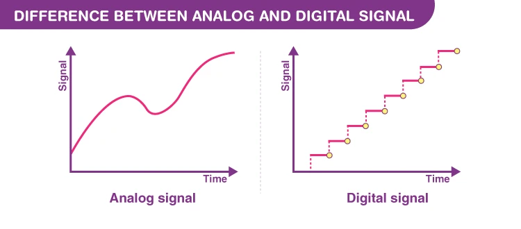
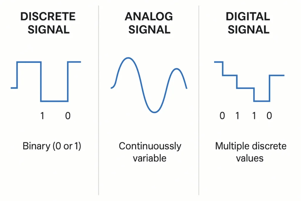
**Analog Signal vs. Digital Signal**
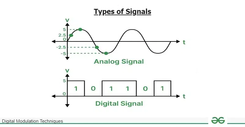
An continuous signal shows a physical quantity that can change smoothly. This includes things like voltage, current, or frequency. It can take any value within a set range.
A digital recording signal encodes information using two values: 0 and 1. These values show changes between “high” and “low” states.
Think of lighting a lamp as an example. An continuous signal is like a dimmer knob. It lets you control brightness from dim to bright.
A digital signal representing works like a toggle switch. It has only two states: fully on or off. Analog signals are continuous change smoothly across a range of options, while digital signals work with fixed states.
The choice between analog and digital signals depends on how they will be used. Digital signals are generally easier to copy and less prone to errors. Any disturbances that affect an continuous signal change the signal itself.
This makes them hard to remove. Digital signals are made to recognize only specific values as important continuous data. This makes it easier to find and fix interference.
Digital signals are rarely perfect. They have limits on how much detail they can show. Analog signals also have issues. They can be affected by interference and lose quality when copied.
The overall effect of flaws in analog systems grows over continuous time. In contrast, these flaws have little impact on digital systems.
Continuous signals are very important in many industrial uses. They help find, measure, and change physical amounts into electrical signals.
These signals can then be processed and analyzed. Here are some common tools and meters used in factories. I will explain what each one is for:
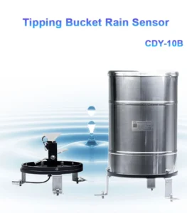
**Pressure Sensors**
Pressure sensors are devices that change pressure from gas or liquid into signals. These signals can be pneumatic or electric. They are used for control, monitoring, and remote transmission. Among these, electric signals are the most widely used.
They convert the measured pressure into standard analog signals. These include 4 to 20 mA current signals and 0 to 5V or 0 to 10V voltage signals.
These output signals can be used by other tools, such as alarms, recorders, or regulators. This helps make sure measurements are accurate. It also helps with monitoring and adjustments on-site.
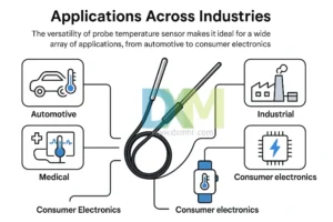
**Temperature Sensors**
Temperature sensors use thermocouples and thermal resistors to measure temperature. The signal from these parts goes into a transmitter. This module converts raw data into a useful continuous signal.
The signal is connected to the measured temperature through a few steps. These steps include stabilizing the circuit, filtering, amplifying, correcting nonlinearity, and converting voltage to current (V/I). This makes it good for monitoring and control in real time.
**Water pH Sensors**
pH sensors use glass electrodes. They measure differences that relate to the amount of hydrogen ions in water. The output is directly related to the water’s pH value. It changes by about 59.16 mV for each pH unit at 25°C.
After amplification with a high input impedance circuit, the signal is changed into an analog voltage range. This range is usually ±414 mV. It lets us monitor pH changes all the time varying.
This process makes sure that systems get accurate chemical analysis. It helps with reliable collection and transmission.
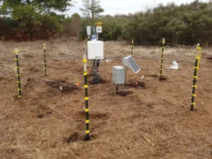
**Water Level Sensors**
Liquid level sensors measure how high a liquid is by using static pressure. This pressure is directly linked to the height of the liquid.
These sensors use strain gauges to detect changes in static pressure. This makes a sensitive diaphragm bend a little, which changes the resistance values.
The signal is made stronger. The device sets the temperature and is ready to use. Then, it is changed into an analog output for monitoring fluid levels.
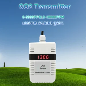
**Gas Sensors**
Gas sensors or detectors measure how much of one or more gases is present in industrial settings. They are mainly split into two types: catalytic detectors and infrared optical detectors.
Catalytic gas detectors use platinum wires. These wires are made of a special metal. When gas burns on these heated wires, their resistance changes. This change in resistance is connected to how much gas is present.
This system provides a steady analog output. It helps track gas levels in unsafe conditions.
Each sensor plays a key role in capturing real-time physical data. It changes this data into analog signals. These signals help keep operations precise and safe in industrial processes.