The differences between wind speed sensors and air volume sensors
Distinguishing between a wind speed sensors and an air volume sensor begins with understanding wind speed and air volume.
We define wind speed as the rate at which air moves relative to a stationary point on Earth. It is typically measured in meters per second (m/s), where 1 m/s equals 3.6 km/h.
Unlike wind, which is categorized into grades, wind speed itself does not have grades but serves as the foundation for classifying wind grades. In general, a higher wind speed indicates a higher wind level and greater potential for destruction.
Wind speed is a crucial parameter in climatological studies. Measuring wind in the atmosphere is important for studying climate change. It also helps in the aerospace industry and military operations.
Air volume denotes the quantity of air moving within a specific time frame. People typically use it to express the capacity of a blower or ventilation system. The measurement unit is cubic meters per second.
When looking at a heat sink made from the same material, air volume is the main factor. It helps us understand how well an air-cooled radiator can release heat.
Clearly, a larger air volume results in a higher heat dissipation capacity for the radiator. This is because the heat capacity of air stays the same. A larger air volume means more air can remove heat faster. Naturally, the effectiveness of heat dissipation also depends on the airflow pattern, even when the air volume remains constant.
Wind speed and air volume are distinct concepts, yet they share a certain relationship. You calculate air volume by multiplying wind speed by the cross-sectional area of the opening. Consequently, researchers often derive air volume sensor data from wind speed sensor measurements.
The precise conversion formula is:
L(m/h) = 3600 * F(㎡) * V(m/s)
In this equation, L stands for the air volume. F represents the ventilation area of the opening. V is the average wind speed measured at the opening.
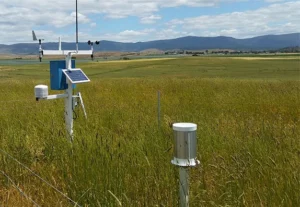
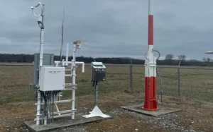
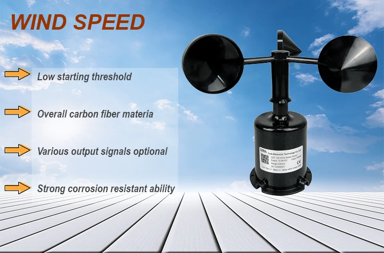
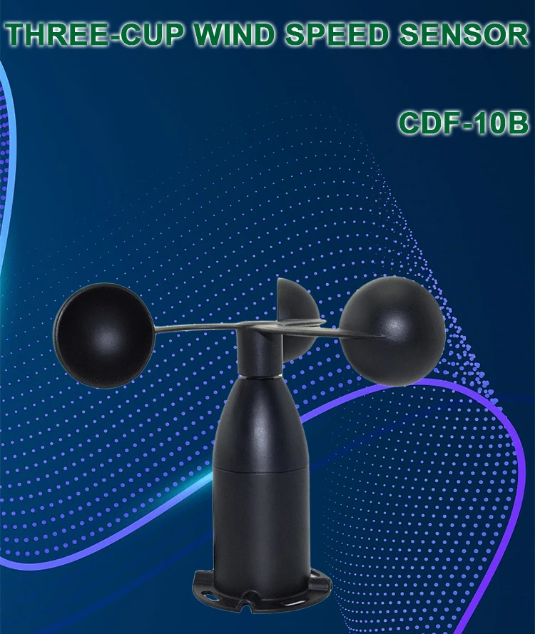
Wind speed sensors
The wind-cup wind speed sensor is a common tool for measuring wind speed. Ruby Sun invented it in England.
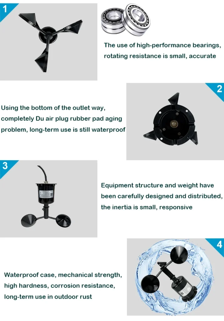
Its sensing component consists of three or four hollow, cone-shaped, or hemispherical cups. Someone mounts these cups on star-shaped brackets with three points, each forming a 120° angle, or on cross-shaped brackets with 90° angles. The cups have concave sides that face the same way. The whole assembly is on a vertical axis, which lets it rotate freely.
When the wind comes from the left, wind cup 1 lines up with the wind. This means the wind’s pressure on wind cup 1 is almost zero in the direction that matches its axis.
Wind cups 2 and 3 intersect the wind’s path at a 60-degree angle. For wind cup 2, the concave side faces the wind. This side feels the highest wind pressure.
In contrast, wind cup 3 has its convex side facing the wind. This means it feels less wind pressure because of the wind’s turbulence. – Wind cup 3 has less pressure than wind cup 2. This pressure difference makes the wind cup assembly rotate clockwise. As the wind speed increases, the initial pressure difference also increases. This results in greater acceleration, causing the wind cup to spin more rapidly.
Design principle of wind speed sensor
Once the wind cup begins to spin, cup 2 turns in the wind’s direction, leading to a relative decrease in wind pressure. Conversely, cup 3 rotates at the same pace but against the wind, resulting in a relative increase in wind pressure.
As time goes on, the wind pressure difference slowly decreases, assuming the wind speed stays the same. Eventually, the pressure difference on the three wind cups becomes zero. At this point, the wind cups will spin at a consistent speed.
You can find the wind speed by measuring how fast the wind cup spins. This means counting the number of spins each second.
As the wind cup spins, it makes the cutting disc or magnetic rod rotate. This creates a pulse signal that matches the wind cup’s speed in the circuit. A counter tallies this pulse signal, and the system determines the actual wind speed after conversion.
Currently, the latest rotor anemometer uses three cups, with the conical cup outperforming the hemispherical cup. When wind speed rises, the rotor cup can swiftly accelerate to match the airflow speed. Conversely, when wind speed decreases, inertia affects the speed, preventing an immediate drop.
In windy conditions, the rotary anemometer often shows a wind speed that is too high. This leads to a large error, averaging about 10%.