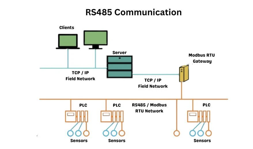
RS485 Communication Overview and Practical Applications
To understand RS485 communication, it’s essential to first grasp the concept of communication itself. Essentially, communication involves sending binary codes (0s and 1s) between two devices. A 0 means a lower signal level. A 1 means a higher signal level.
For example, when a PLC sends data to two inverter slaves (slave 1 and slave 2), you must first connect the slaves. Once the hardware connection is set up, inverter slave 1 may generate a code sequence like 101010. It then sends matching high and low signals through its communication port.
The cable carries the signal to the communication port on inverter slave 2. Slave 2 receives the signal.
It converts the signal back into the original binary sequence (101010). This completes the data transfer between the PLC and the two inverter slaves.
Key Concepts in Communication:
**1. Full-Duplex and Half-Duplex**
Full-duplex is a communication mode where a device can send and receive data at the same time. In contrast, half-duplex lets a device send or receive data at one time, but not both.
Simplified illustration:
– Full-duplex: Like a phone call, both parties can speak and listen at the same time.
– Half-duplex: Like a walkie-talkie, only one person can talk at a time. The other person listens.
– Single-duplex: A one-way mode where one device sends data. The other device only receives it. It cannot send data back.
**2. Communication Rate**
The communication rate, often called the baud rate, is the number of bits or signal changes sent per second through a port.
For example, if the communication rate is 9.6 Kbps, the port can send 9,600 bits each second. This includes both high and low signal levels.
**3. Bit Transmission Rate**
The bit transmission rate is the total information sent each second through a communication channel.
It is denoted as rb and measured in bits per second (b/s).
**4. Master-Slave Communication Model**
The master-slave model defines roles in a network. One device is the master. Other devices act as slaves. Communication occurs directly between the master station and each slave station, but not between two slave stations without routing through the master station.
Simplified differentiation of roles:
– Commands:
– Master station: Actively sends commands to slave devices.
– Slave station: Passive. Responds, but does not start commands.
– Uniqueness:
– Master station: Always unique; there is only one master when operating the network.
– Slave station: Can exist in multiples within a single system.
– Connectivity:
– Master station: Capable of communicating with several slave stations.
– Slave station: Each slave communicates only with its assigned master station.
RS485 Communication Basics:
Here are four core aspects of RS485 communication:
**Communication Medium**
RS485 uses shielded twisted-pair cables to send signals. These cables have two insulated wires and a protective shield. The shield reduces interference and helps ensure reliable signal transmission.
**Communication Method**
RS485 mainly uses half-duplex mode, so devices send or receive data one at a time.
**Communication Type**
The system uses a master-slave setup for network management and data communication flow.
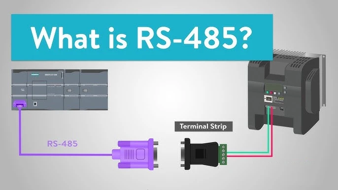
**Physical Layer**
The physical connection for RS485 communication uses a 9-pin interface. However, only pins 3 and 8 are used in practice.
Pin 3 carries the “-” (negative) signal, and pin 8 carries the “+” (positive) signal.
Using an example to make it clearer: Imagine two people talking on a phone call. The phone is the physical layer that enables communication, while their spoken language is the protocol sent through it.
Similarly, RS485 provides the physical layer. It can support many communication protocols, like Modbus or Profibus. This is like using different languages on the same telephone system. This analogy shows the link between physical layers and communication protocols in RS485 technology.
Conclusion
RS485 is a standard. It defines the electrical properties of transmitters and receivers. It is used in balanced, digital, multi-drop communication systems. And it is maintained by the Telecommunications Industry Association (TIA) and the Electronics Industry Alliance (EIA).
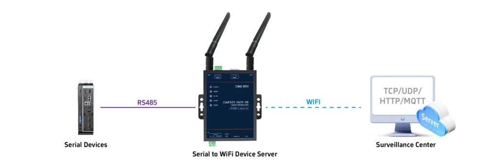
Digital RS485 networks send signals well over long distances, even in places with high electrical interference. It enables the creation of cost-effective local networks and multi-branch communication setups.
RS485 supports two connection types: two-wire and four-wire systems. The four-wire setup allows for point-to-point communication but is seldom used today. Instead, the two-wire method is now more common.
This approach employs a bus topology structure, supporting up to 32 nodes on the same network bus. Typically, RS485 networks use a master-slave model. One device acts as the master, and the rest act as slaves.
When setting up an RS485 link, it is common to connect the “A” and “B” terminals with twisted pair wires. Many setups omit the signal ground connection. While this method often works in specific scenarios, it introduces significant risks.
One major issue is common-mode interference. RS485 interfaces use differential signaling. They detect the voltage difference between two wires. They do not reference a specific ground point.
However, the transceiver works within a common-mode voltage range of -7 V to +12 V. If the network’s common-mode voltage exceeds this range, it may reduce communication stability and reliability. It may even damage the interface.
The second issue comes from electromagnetic interference (EMI). The driver’s output signal often has a common-mode part that needs a return path. Without a low-resistance return path (signal ground), this energy may spread out as electromagnetic radiation.
This makes the whole bus act like a huge antenna. It sends out electromagnetic waves and may disrupt nearby electronics.