


Description
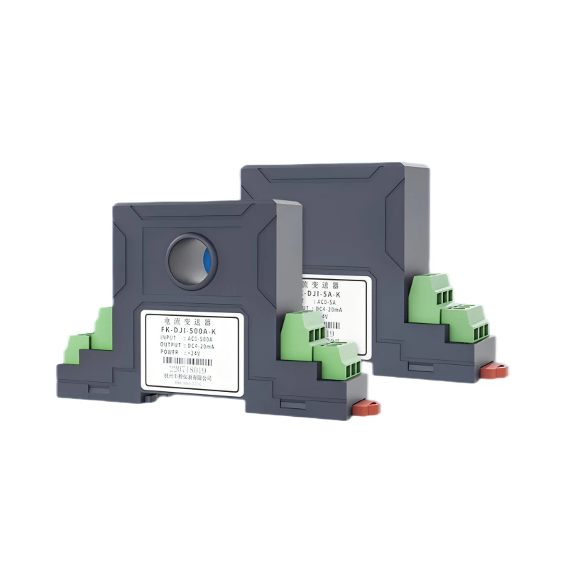
CDP-1T0A HALL EFFECT CURRENT SENSOR & DC VOLTAGE DETECTOR
Overview
The Hall current sensor operates based on the magnetically balanced Hall principle. According to the Hall effect principle, when the primary side current (Ip) passes through a wire, a magnetic field is generated around the wire. The size of this magnetic field is proportional to the current flowing through the wire. The core aggregates this magnetic field to the Hall device and enables it to have a signal output. The signal is amplified by the signal amplifier and output directly. The output signal of the Hall device accurately reflects the output of the primary current.
Key Features
• Fast dynamic response <300ms, instantly captures transient changes of DC circuit current and voltage.
• Dual-parameter integrated detection, simultaneously monitors DC current (0-150A) and DC voltage (0-500V)
• High measurement precision up to ±0.5%, low temperature drift of 300ppm/℃
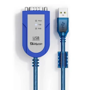
• Multiple standard signal outputs: 4-20mA analog signal + RS485 digital communication
• Wide operating temperature range: -10℃~+60℃
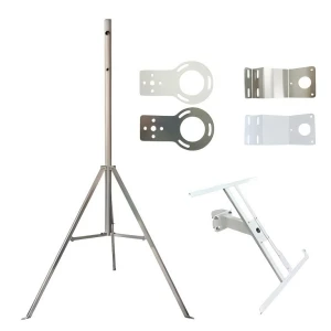
Select Options
Related Products
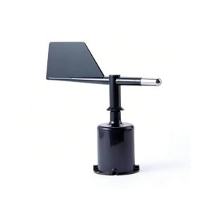
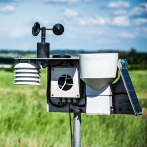
ABS Wind Direction Sensor
High-precision wind direction sensor with durable ABS housing, designed for reliable environmental monitoring in harsh weather conditions.
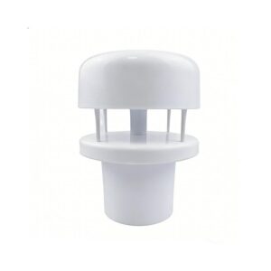
Miniature Ultrasonic Wind Speed And Direction Sensor
This high-performance Miniature Ultrasonic Wind Speed and Direction Sensor is engineered for compact, low-power, and maintenance-free wind monitoring in IoT, weather stations, and industrial applications.
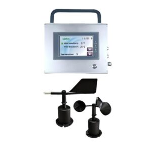
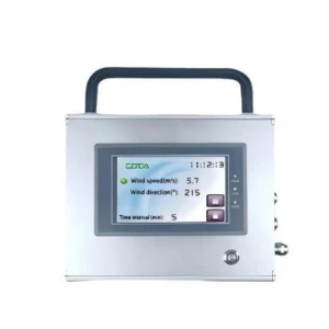
Wind Speed & Direction Display Recorder
This display shows the date, time, wind speed, and direction. We include a large flash memory chip. It can store automatic weather data logging interval for at least three year.
NEWS Application
Smart Agriculture
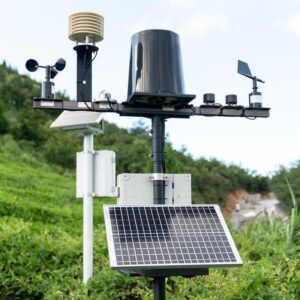
ABS wind speed meter serve as a critical environmental data foundation for smart agriculture, delivering real-time, accurate airflow measurements across open fields, greenhouses, and orchards.
Photovoltaic Industry
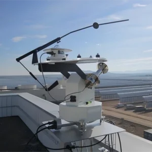
Wind speed sensors or anemometer play a critical role in the safe, efficient, and intelligent operation of photovoltaic (PV) power stations.
Environmental Monitoring
Integrated into urban environmental monitoring networks, industrial IoT systems, and weather stations to support pollution diffusion analysis, microclimate research, and smart city management.