

Why do sensors utilize the 4-20mA current signal?
The 4-20mA current signal is often used in industrial sensors and transmitters. These devices measure things like temperature and humidity. These devices change physical amounts into electrical signals.
This makes it easy to measure, process, and share data. Here is why we choose the 4-20mA range. It also covers how we manage long-distance transmission.
Why Use 4-20mA Current?
1. **Resistance to Interference**:
Current signals are strong against electromagnetic interference. This quality makes them great for industrial uses. Current signals are clear and strong, even in loud places. This is not the same as voltage signals.
2.**Accuracy Over Distance**:
A current source has very high internal resistance. This means that resistance from wires or connections does not change how accurate the measurements are. This allows reliable transmission over hundreds of meters using ordinary twisted-pair cables.
3. **Explosion-Proof Design**:
The maximum current of 20mA was selected to meet safety rules for explosion-proof needs. Even if sparks happen from turning the device on and off, they do not have enough energy to ignite flammable gases.
4. **Disconnection Detection**:
Setting the lower limit to 4mA helps detect faults. This is better than setting it to 0mA. It helps to find issues when the cable is not plugged in.
A normal signal stays above 4mA. If the connection is broken, the current drops to 0mA. Often, a threshold like 2mA is used as a disconnection alarm value.
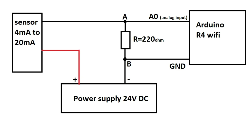
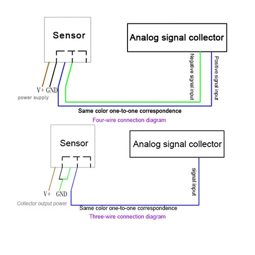
5. **Two-Wire System**:
The 4-20mA protocol uses a two-wire setup. These wires give power and send signals. The minimum current of 4mA gives enough power for the transmitter to work.

Transmission Distance of 4-20mA Signals
Many things influence how far a 4-20mA signal can go.
1. **Excitation Voltage**:
The voltage supplied to the transmitter must be high enough to keep the circuit working.
2. **Minimum Operating Voltage of Transmitter**:
This states the minimum voltage needed for the transmitter to work correctly.
3. **Voltage Across Sampling Resistor**:
The resistor in the receiving device affects the total voltage drop in the circuit.
4. **Wire Resistance**:
The resistance of the cable depends on what it is made of, how long it is, and its thickness.
We can use these variables to estimate the farthest distance for transmission.
Example Calculation:
Assume:
– Supply voltage (Ue) = 24V
– Current (I) = 20mA
– Sampling resistor (RL) = 250Ω
– Minimum operating voltage (Umin) = 12V
The maximum wire resistance (r):
\[ r_{\text{max}} = \frac{Ue – Umin – (I \times RL)}{I} \]
[ r_{\text{max}} = \frac{24 – 12 – (20 \times 0.25)}{0.02} \]
Using copper wire with resistivity (ρ) of 0.017Ω·mm²/m and wire cross-section (S) of 1mm²:
\[ L = \frac{r}{\rho} \]
\[ L = \frac{175}{0.017} \approx 10,294\ m \]
In ideal conditions, a 1mm² copper wire can send a 4-20mA signal over more than 10 kilometers. This distance changes with different voltages, transmitter details, and wire features.
Why Is DC Voltage Unsuitable for Long Distances?
The standard *GB/T 3369.2-2008* explains why analog DC voltage signals are not good for long-distance transmission. Voltage signals get weaker as they move and are greatly affected by electromagnetic interference.
Current signals stay strong and are less affected by outside factors over long distances. This reliability is why the industry likes current-based protocols, such as 4-20mA, for process control systems.
In summary
4-20mA is a good choice for several reasons. It is strong and accurate. And it is also safe to use. It can also communicate over long distances in industrial settings.