How to Read Data from a Modbus RS485 Temperature Sensor
In industrial and commercial applications, accurately monitoring temperature is crucial. Many users widely utilize Modbus RS485 Temperature Sensor because they offer reliability and can communicate over relatively long distances. This article will guide you through the process of reading data from such a sensor.
Understanding Modbus and RS485
Modbus Protocol
Modbus is a protocol for serial communication. It lets smart devices, like sensors and controllers, talk to each other.
There are two main modes: ASCII and RTU (Remote Terminal Unit). The RTU mode is more popular. It has higher data density and faster speeds.
In Modbus RTU, data is sent in binary format. Each data frame has four parts. These are the address field, the function code field, the data field, and the cyclic redundancy check (CRC) field.
RS485 Interface
RS485 is a standard for serial communication at the physical layer. It uses a method called differential signaling. This means it sends data through two wires, A and B.
This type of signaling helps reduce noise and allows for longer communication distances than other serial interfaces, like RS232. RS485 also supports multi-drop communication. This means many devices can connect to the same bus. It is great for situations where many sensors connect to one main device.
Hardware Setup
Connecting the Temperature Sensor
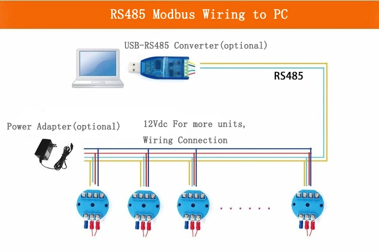
Power Connection: First, make sure the Modbus RS485 temperature sensor is powered correctly. Most sensors work with a specific DC voltage, like 12V or 24V. Connect the positive and negative power supply wires to the right terminals on the sensor.
RS485 Wiring: Connect the RS485 output from the temperature sensor to the RS485 interface of the master device. This could be a PLC, a MCU with an RS485 module, or a PC with an RS485 adapter. Connect the A wire of the sensor to the A wire of the master device.
Then, connect the B wire of the sensor to the B wire of the master device. In some cases, there may be a ground wire (GND). This wire should connect to the ground of the main device. This connection helps keep the electrical parts separate.
Master Device Setup
PC with RS485 Adapter: If you use a PC as the main device, you need an RS485 adapter. These adapters are often USB-to-RS485 converters. Install the driver software that comes with the adapter.
After you install it, the adapter will show up as a virtual serial port in the device manager. Make sure to note the COM port number assigned to the adapter.
If you are using a PLC or MCU, make sure it has an RS485 communication module. It should also have built-in RS485 features. Set up the communication settings in the PLC or MCU programming area.
This includes the baud rate, data bits, parity, and stop bits. These settings must match those of the temperature sensor.
Configuration
Sensor Configuration
Address Setting: Each Modbus device on the network needs a unique address. The temperature sensor can often set its address with dip switches or software. Make sure to set the temperature sensor’s address to a value that is not in use on the RS485 network. For example, if there are no other devices on the network yet, you can set the sensor’s address to 1.
Communication Settings: The sensor needs to be set up with the correct communication settings. This includes the baud rate, such as 9600, 19200, or 38400 bps.
It also includes data bits, which are typically 8 bits long. Parity can be none, even, or odd. Lastly, there are stop bits, which are usually 1 or 2 bits. These settings must match the master device’s settings for successful communication.
Master Device Configuration
Software Configuration: If you are using a PC with Modbus master software like Modbus Poll, open the software. Then, set up the following settings:
Choose the COM port that matches the RS485 adapter.
Baud Rate, Data Bits, Parity, Stop Bits: Set these values to match the settings of the temperature sensor.
Slave Address: Enter the address of the temperature sensor that you set in the previous step.
To program a PLC or MCU, you must write code. This code will help it talk to the temperature sensor. In the code, you will set up the RS485 communication interface. Make sure to use the right parameters.
Then, use Modbus functions to read data from the sensor. For example, a Python program can use the pymodbus library. This library helps communicate with a Modbus RTU device.

Reading Data
Using Modbus Function Codes
To read the Modbus RS485 Temperature Sensor, the master device sends a Modbus query. It uses the right function code. The most common code for reading data from a holding register is code 03.
This is where the temperature value is usually stored. The master device has the starting register address and the number of registers to read in the query. The sensor gives back the data saved in those registers.
Data Interpretation
Once the master device gets the data from the sensor, it must interpret it correctly. The temperature is saved as a raw binary number. The sensor’s datasheet gives details on how to convert this raw value into a real temperature reading.
For example, you may need to divide the raw value by a certain number. You may also need to change it to show the temperature in Celsius or Fahrenheit.
Troubleshooting
Communication Errors
Check the wiring. Make sure all connections are secure. Look for any loose wires.
– Check the configuration.
– Ensure the communication settings are correct. This includes baud rate, data bits, parity, and stop bits.
– Verify that the device addresses are correct on both the sensor and the master device.
Power Issues: Make sure that both the sensor and the master device are receiving proper power.
Incorrect Data Readings
Calibration: Check if the sensor needs calibration. If the readings are often wrong, you may need to calibrate it.
Register Mapping: Make sure you read the right registers. The sensor’s datasheet should clearly show which register holds the temperature data.