

Connecting Sensors to Arduino Modules
Introduction
Arduino modules, an open – source electronics platform, has revolutionized the way hobbyists, students, and professionals approach electronics projects. One of its most powerful features is the ability to interface with a wide variety of sensors. Sensors allow Arduino to interact with the physical world, collecting data such as temperature, light, humidity, and motion. This article will provide a comprehensive guide on how to connect sensors to an Arduino modules.
Step 1: Gather Your Materials
Before you start the connection process, you need to have the right materials on hand.
Arduino Board: There are different types of Arduino boards, such as Arduino Uno, Mega, and Nano. Choose the one that suits your project requirements.
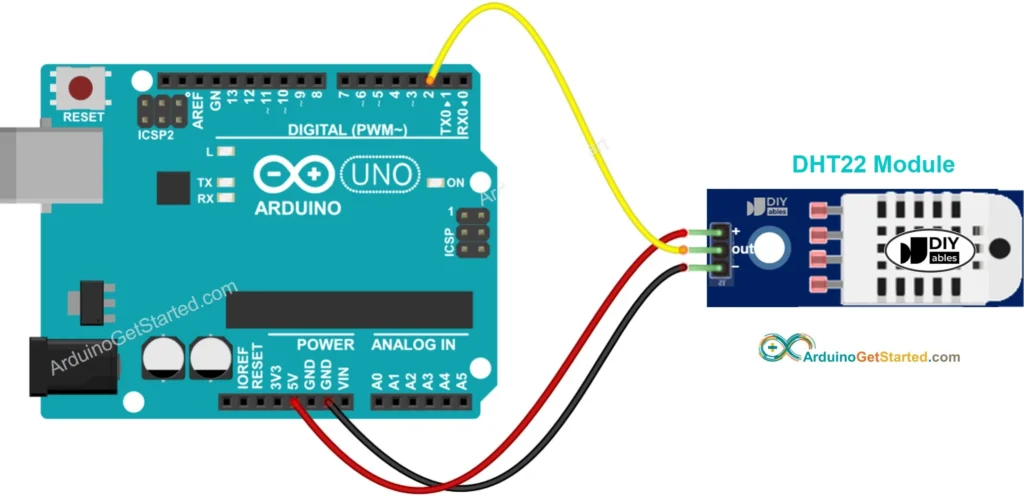
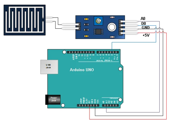
Sensor: Select a sensor based on what you want to measure. For example, if you want to measure temperature, you can use a DHT11 or DHT22 sensor; for light detection, a photoresistor or an LDR (Light – Dependent Resistor) is a good choice.
Breadboard: A breadboard is a useful tool for prototyping circuits. It allows you to make temporary connections without soldering.
Jumper Wires: These are used to connect the Arduino board, the sensor, and other components on the breadboard.

Step 2: Understand the Sensor
Each sensor has its own datasheet, which is a document that provides detailed information about the sensor, including its pinout, electrical characteristics, and operating principles.
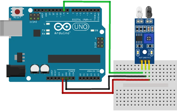
Pinout: The pinout shows which pins on the sensor are used for power, ground, and signal output. For example, a typical sensor may have a VCC pin for power, a GND pin for ground, and an OUT or SIG pin for the signal output.
Electrical Characteristics: This includes the voltage requirements of the sensor. Some sensors operate at 5V, while others may work at 3.3V. Make sure your Arduino board can provide the appropriate voltage.
Step 3: Connect the Power
Connecting the power is a crucial step.
Positive Terminal: Locate the VCC or power pin on the sensor. Use a jumper wire to connect this pin to the 5V or 3.3V pin on the Arduino board, depending on the sensor’s voltage requirements.
Negative Terminal: Connect the GND (ground) pin on the sensor to the GND pin on the Arduino board. This creates a common electrical reference point for the circuit.
Step 4: Connect the Signal
The signal connection allows the Arduino to receive data from the sensor.
Digital or Analog Signal: Determine whether the sensor outputs a digital or an analog signal. Digital signals are either high (5V) or low (0V), while analog signals can have a continuous range of values.
Pin Selection: If it is a digital signal, connect the sensor’s signal output pin to one of the digital input pins on the Arduino board (e.g., D2 – D13). For an analog signal, connect it to one of the analog input pins (A0 – A5).

Step 5: Write the Code
After the hardware connection is complete, you need to write a program to read the sensor data.
Arduino IDE: Open the c. It is a software application that allows you to write, compile, and upload code to the Arduino board.
Example Code: Here is a simple example of reading data from an analog sensor (e.g., a photoresistor) connected to analog pin A0:
const int sensorPin = A0;

void setup() {
  // Initialize serial communication at 9600 baud rate
  Serial.begin(9600);
}

void loop() {
  // Read the analog value from the sensor
  int sensorValue = analogRead(sensorPin);

  // Print the sensor value to the serial monitor
  Serial.print("Sensor value: ");
  Serial.println(sensorValue);

  // Wait for a short period before reading the sensor again
  delay(1000);
}
Upload the Code: Connect your Arduino board to your computer using a USB cable. Select the correct board and port in the Arduino IDE, and then click the upload button to transfer the code to the Arduino board.
Step 6: Test the Connection
Once the code is uploaded, open the serial monitor in the Arduino IDE. You should see the sensor data being printed continuously. If the data is not as expected, check the following:
Hardware Connections: Make sure all the jumper wires are properly connected and there are no loose connections.
Code Errors: Review the code for any syntax errors or logical mistakes.
In conclusion, connecting sensors to an Arduino module is a relatively straightforward process if you follow these steps. With the right materials, understanding of the sensor, proper connections, and appropriate code, you can create a wide range of projects that interact with the physical world.